Planar coordinate system
Introduction
Planar coordinate systems locate data on the flat surface of a map in a 2D space. This includes 2D Cartesian Coordinates and 2D Polar Coordinates.
Explanation
A flat map has only two dimensions: width (left to right) and length (bottom to top). Transforming the three dimensional Earth onto a two-dimensional map is the subject matter of map projections and coordinate transformations. Here, as for several other cartographic applications, two-dimensional Cartesian coordinates (x, y), also known as planar rectangular coordinates, describe the location of any point unambiguously.
2D Cartesian Coordinate System (X,Y)
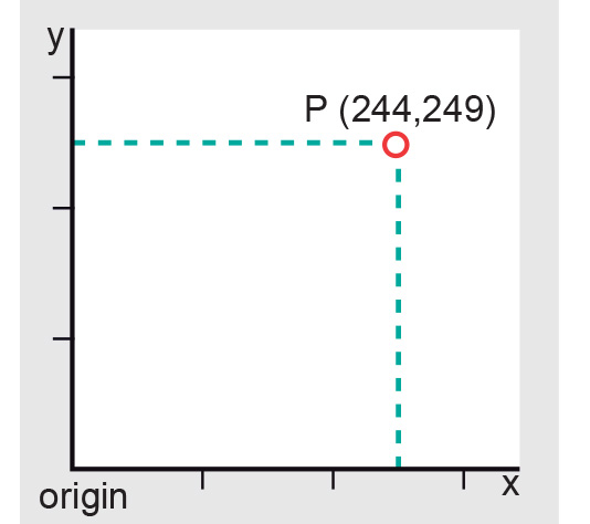
The 2D Cartesian coordinate system is one of intersecting perpendicular lines with the X-axis and the Y-axis as principal axes. The X-axis (the Easting) is the horizontal axis and the Y-axis (the Northing) is the vertical axis with an intersection at the origin. The plane is marked at intervals by equally-spaced coordinate lines that together form the map grid . Given two numerical coordinates x and y for point P, one can unambiguously specify any location P on the map (Figure 1).
Usually, the origin is assigned the coordinates x = 0 and y = 0. Sometimes, however, large positive values are added to the origin coordinates. This is to avoid negative values for the x and y coordinates in cases where the origin of the coordinate system is located inside the specific area of interest. The point that then has the coordinates x = 0 and y = 0 is called the false origin.
The grid on a map represents lines having constant 2D Cartesian coordinates. It is almost always a rectangular system and is used on large- and medium-scale maps to enable detailed calculations and positioning. The map grid is usually not used on small-scale maps (about 1:1,000,000 or smaller). Scale distortions that result from transforming the Earth’s curved surface to the mapping plane are so great on small-scale maps that detailed calculations and positioning become difficult.
2D Polar Coordinate System (α, d)
Another way of defining a point in a plane is by using polar coordinates. This is the distance d from the origin to the point concerned and the angle α between a fixed (or zero) direction and the direction to the point. The angle α is called azimuth or bearing and is measured in a clockwise direction. It is given in angular units while the distance d is expressed in length units.
Bearings are always related to a fixed direction (initial bearing) or a datum line (Figure 2). In principle, this reference line can be chosen freely. Three different, widely used fixed directions are: True North, Grid North and Magnetic North. The corresponding bearings are true (or geodetic) bearings, grid bearings and magnetic (or compass) bearings, respectively.

Polar coordinates are often used in land surveying. For some types of surveying instruments, it is advantageous to make use of this coordinate system. The development of precise, remote-distance measurement techniques has led to a virtually universal preference for the polar coordinate method for detailed surveys.
Examples
Example of a 2D Cartesian Coordinate System:
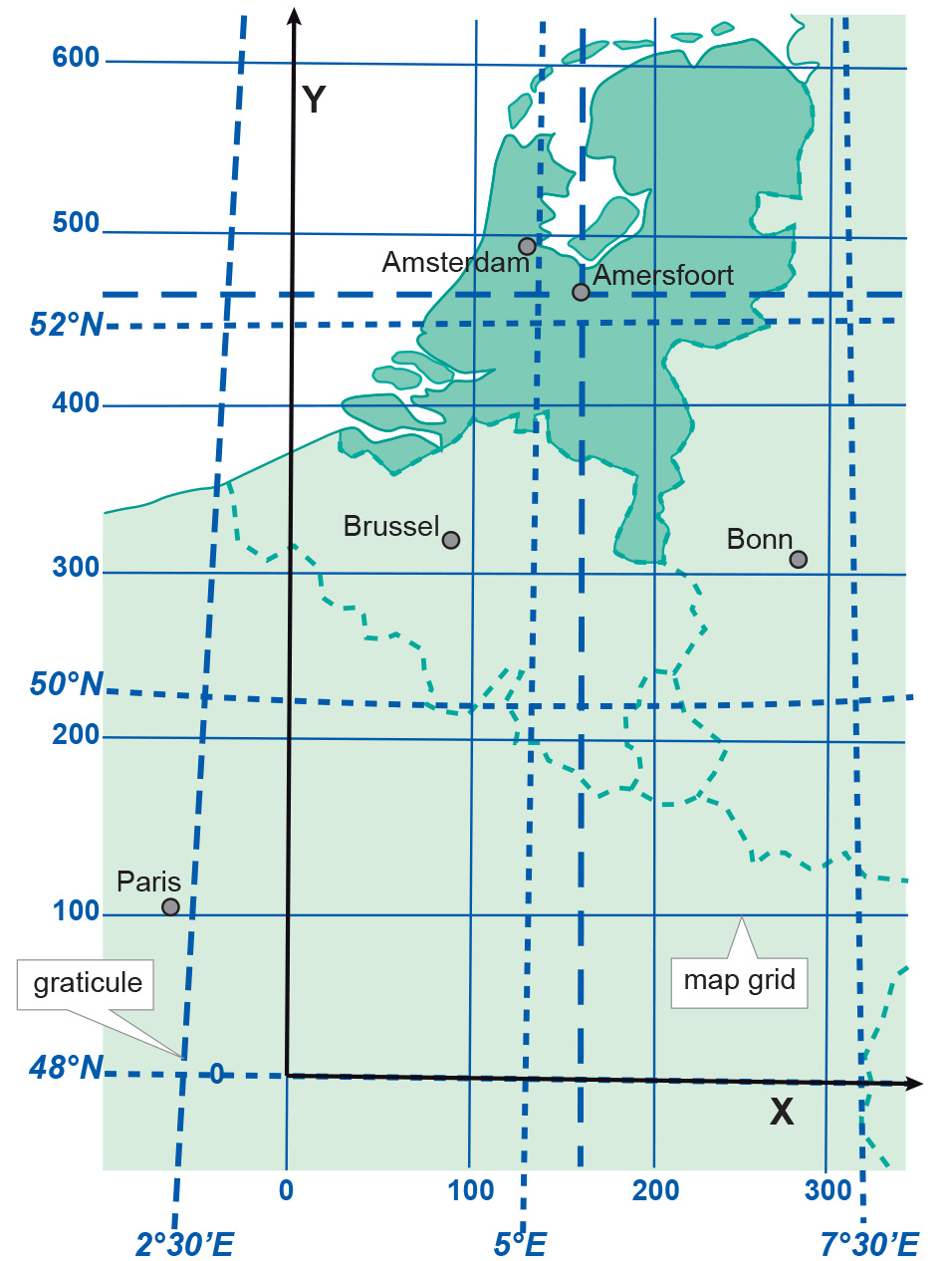
The Rijksdriehoekstelsel (RD) in the Netherlands is an example of a 2D Cartesian Coordinate System with a false origin (Figure 3). The system is based on the azimuthal double stereographic projection, with the Bessel ellipsoid used as reference surface. The origin was shifted from the projection centre (Amersfoort) towards the southwest (false origin) to avoid negative coordinates inside the country.
Learning outcomes
-
7 - Coordinate systems and map projections
Explain the relevance of reference surfaces, coordinate systems, and coordi-nate transformations in mapping (level 1 and 2).
Prior knowledge
Outgoing relations
- Planar coordinate system is a kind of Coordinate system
Incoming relations
- Map projection is a kind of Planar coordinate system
- Geographic coordinate system is used by Planar coordinate system